Troubleshooting Manual
All Heatline boiler models are all wall- mounted, fan flued condensing type of boilers capable of supplying both mains fed domestic hot water and central heating. Those appliances are not suitable for external installation unless protected by a purpose made building such as a boiler house. Those appliance can be installed in any room or internal compartment without the need for purpose made combustion ventilation. Naturally in instances where you appliance is installed in a compartment we recommend that your compartment is ventilated for boiler cooling purposes. If you plan to install your boiler in a room containing a bath or shower then you need to make sure that shower or bath user will not touch any electrical parts or power supply by any parts of his body and that the installation fulfills all requirements of latest British Standard and Building Regulations.
We recommend to keep following clearances for ventilation purposes: 300 mm below, 200 mm above, 50 mm at each side. You can open the cupboard door or provide a 600 mm clearance at the front. Your appliance has to be sited at least 1 meter away from any flammable products. Pay attention to the fact that heat sensitive walls need to be protected by an appropriate insulating material. The wall on which your appliance will be mounted should be able to support the weight of the boiler for an extensive period of time. A condensate drain pipe should be installed in order to take the condensate discharge. The preference is that condensate material should be discharged into the household internal drainage system. We recommend to increase diameter of the external condensate pipe to 32 mm to prevent the condensate from freezing. The compartment must be big enough to allow normal servicing and/ or boiler’s removal or parts replacement.
Warning! When the boiler is intended for use with LPG it must not be installed in a room or internal space below ground level!
Boiler normal operation
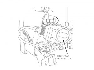
Your appliance can be set to work either on domestic hot water and heating or domestic hot water only. Naturally domestic hot water demand will draw temporary preference over the heating for the time of how water demand and 3 min cooling period. Depending on demand water is either circled by the three port valve to the secondary water-to-water heat exchanger for domestic hot water or directly to the heating system.
Domestic hot water mode
On opening a hot water outlet the boiler automatically responds to fire the boiler and supply the water-to-water heat exchanger with hot water via the three port valve. Port valve can be found on the hydro-block. The electronic control will adjust the burner’s output to keep the temperature as required. Hot water will flow till the faucet is closed. Pump will run for a additional 10-15 secs in order to release the heat from the boiler itself. The water circulation is shown on the picture below
Central heating and domestic hot water mode
When heating demand is requested, power is on and the thermostats are calling for heat, the boiler fires. A builtin pump is powered and hot water start to circulate around the central heating pipe system and radiators. When the demand for central heating is fulfilled, the burner will shut down and the appliance will come to stand-by mode, until the next hot water or heating demand. The pump will operate for 10-15 seconds to release the heat from the boiler itself. Hot water demand will take heating mode whenever hot water tap is opened. Normal central heating functionality will come back once hot water tap is closed. A delay up to 45 sec may be observed- depending on a model.
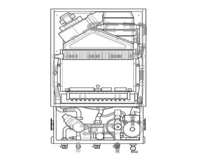
Boiler parts
Each Heatline boiler is equipped with following additional parts:
- An interface unit, which includes boiler adjustment potentiometers and fault display provides easy service ability to the boiler. Heat transfer to the boiler’s primary hydraulic circuit is obtained via a primary, gas to heat exchanger located within a combustion chamber that is hermetically sealed. A 230 volt, duel speed fan expels combutsion products from the chamber to outside air via an associated flue system. The fan is activated at the beginning of each ignition cycle. Its operation is being controlled by positive and negative sensing points located on the the air pressure switch
- An electronic control unit, consisting of a PCB that consists of an ignition module that is responsible for igniting the burner and supervision of flame along with gas supply modulation to the burner
- In the boilers main hydraulic circuit an integral pump is located. The purpose of integral pump is to circulates the water via primary heat exchanger to domestic hot water and/ or the central heating circuit. We recommend to use a by-pass system in instances where reduced or interrupted water circulation was observed in the past
- A secondary heat exchanger allows the instantaneous transferred of heat from the primary circuit to domestic hot water circuit
- Room temperature can be controlled by the use of a temperature regulator or an external room thermostat. The room thermostat connection dependents from the thermostat operating voltage
Error codes
The appliance’s control panel has builtin LED display, which shows operation state and fault defect codes. Fault memory will allow you to display up to 10 most recent fault codes
Table 1. Most common Heatline faults based on error code message
| Fault code | Description | Solution |
| F00 | Flow heating temperature sensor fault | Verify the sensor’s connections. Verify the wiring harness. Verify the sensor |
| F01 | Return heating temperature sensor fault | Verify the sensor’s connections. Verify the wiring harness. Verify the sensor |
| F10 | Flow heating temperature sensor fault | Verify the sensor’s connections. Verify the wiring harness. Verify the sensor |
| F11 | Return heating temperature sensor fault | Verify the sensor’s connections. Verify the wiring harness. Verify the sensor |
| F20 | Overheating fault | Verify the operation of the pump. Verify the wiring harness. Verify that the fl ow and return heating isolation valves are open |
| F22 | Water pressure of the installation | Fill the installation. Purge the installation. Verify the pump connections. Verify the flow and return heating sensor connections. Verify that there are no leaks |
| F23 | Maximum temperature difference reached between return and flow heating | Verify the flow and return heating sensor connection. Verify the pump speed |
| F24 | Water circulation fault | Verify that the fl ow and return heating isolation valves are open |
| F26 | Fault in gas valve motor | Verify the gas valve connections. Verify the operation of the gas valve. Verify the operation of the condensate pump |
| F27 | Flame detection fault | Verify the flame detection electrode. Verify the main board. Verify the igniter unit |
| F28 | Ignition fault | Verify the return gas circuit (gas valve open). Verify the observe the flame picture and Verify the CO setting. Verify the igniter unit connections. Verify the state of the electrode |
| F32 | Incorrect air pressure | Verify the entire flue system. Verify the fan’s electrical connections |
| F49 | EBUS voltage fault | Verify that the eBus controls are fitted and wired correctly |
| F61-67 | Fault in the main board | Verify the main boards connections. Verify the main board. Verify the appliance DSN number is correct. Reset the appliance |
| F68 | Fluctuation of flame signal | Verify the return gas circuit (gas valve open). Verify the observe the flame picture and Verify the CO setting. Verify the igniter unit connections. Verify the state of the electrode . |
| F70 | User interface incompatible with the main board | Verify that the appliance DSN code on the screen matches the product code of the nameplate. Verify the boards reference |
| F71 | Flow heating temperature sensor fault | Verify the sensor connections. Make sure that the sensor is clipped to the tube |
| F72 | Permanent temperature difference between flow and return heating sensors | Verify temperature sensors connections. Replace faulty sensors |
| F73-74 | Heating circuit pressure sensor fault | Verify the sensor’s connections. Verify the sensor |
| F76 | Thermal fuse fault | Verify the fuses connections. Replace the heat exchanger |
| F77 | Fault in gas valve motor | Verify the gas valve connections. Verify the operation of the gas valve. Verify the operation of the condensate pump |
| F83 | No water in the installation: the temperature doesn’t increase when the burner is lit | Fill the installation. Purge the installation. Verify the pump connections. Verify the fl ow and return heating sensor connections. Verify that there are no leaks |
| F84 | Permanent temperature difference between flow and return heating sensors | Verify temperature sensors connections. Replace faulty sensors |
| F85 | Flow and return heating sensors fault | Verify temperature sensors connections |
| F86 | Underfloor heating contact fault | Verify the sensor connections. Verify that the sensor is connected to the main board and the shunt is removed |
| Err | User interface fault | Verify connection from user interface PCB to main PCB. Replace user interface |
Table 2 Central heating and hot water functionality fault finding
| Fault | Action | Solution |
| No hot water | Is the central heating? Yes | Replace flow meter or/and D.H.W. sensor |
| No hot water | Is bar LED illuminating? Yes | Re-pressurize system |
| No central heating | Is there overheat LED illuminating? Yes | Replace overheat thermostats |
| No central heating | Is pump running? No | Check wiring / connections mains voltage |
| No hot water and no central heating | Open a hot tap to create a demand – is there a spark at the ignition electrode? Yes | Replace gas supply, pressure or gas valve |
| No hot water and no central heating | Open a hot tap to create a demand – is there a spark at the ignition electrode? No. Is fan running? Yes | Replace air pressure switch or overheat sensor |
| No hot water and no central heating | Are LEDs on? No | Replace user interface PCB |
| No hot water and no central heating | Is fan running? No | Replace low water pressure switch |
Filling the System
The boiler is operated with water. System pressure need to be charged to the value of around 1.5 bar. To correctly fill in the water into the system you should follow the steps below:
- Open two manual boiler isolation and feed valves
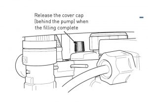
- Unscrew the cover cap of the boiler’s automatic air vent situated on top of the pump
- Close manual feed valves and disconnect the filling loop once the pressure gauge, sited on the boiler’s control panel, indicates a system pressure between 1.0 and 1.5 bar
- Check that all the water connections throughout the system are sound and bleed every radiator. As air is vented the system pressure may need topping back up to 1.0 bar
- Vent the air from the boiler’s pump. You should unscrew the integral pump vent plug. Let the water bleed for a while
- Pay attention not to splash water onto boiler’s electrical components!
Warning! When the system is bled of any air it must be refilled until the pressure shown on the display gauge indicates a system pressure of 1.5 bar. Whenever the pressure shown on the gauge is higher then 1.5 bar you will need to discharge the excess via a pipe connection or a radiator valve. The safety discharge valve shouldn’t be used because it gets easily contaminated with debris and won’t re-seal properly
Attention! Failure to properly flush the heating system while boiler is disconnected or to adding an anti corrosion liquid to the water system water will invalidate the boiler’s warranty. Before putting the appliance into operation remember to drain the plastic discharge pipe
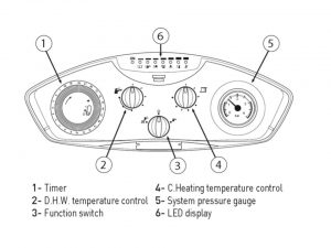
Control panel functions
Central heating and domestic hot water temperature controls
The appliance’s integral control unit adjusts and monitors the applaince’s hydraulic circuit and domestic hot water outlet temperatures by means of sensors located on the central heating and domestic hot water flow outlets. The sensors electrical resistance that dependent on temperature monitors also the current that is going through the control potentiometers. Those potentiometers are placed on the control panel. It is the potentiometer control dial that lets setting manually the temperature from 30º-85ºC for central heating and 30º- 65ºC for domestic hot water. In instances when your appliance operates in heating or domestic hot water mode, the current provided will be compared to the manually pre-set value. The difference of the two values operates the modulation of the gas valve adjusting the useful heat output generated and stabilizing the temperature to within ±1ºC.
Re-set function
Whenever boiler gets locked out, you should verify the gas supply and ionisation probe position. Your boiler can be re-started by switching to standby “O” position and waiting 15-30 seconds and switching back to its previous position once the fault has been eliminated.
Function switch
The three position switch allows the boilers operation to be set to ‘Stand-by’ (cenetr position), ‘Heating + Domestic Hot Water’ (left hand position) or ‘Domestic Hot Water only’ (right hand position)
Onboard Adjustments
Your appliance comes with 4 potentiometers and a few dip switches, thanks to which you can still adjust factory pre-set values. All those are located on the rear of the control panel. If you want to access the the potentiometers you should simply remove the cover panel and you will see those at the rear as shown on the picture below
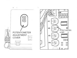
Following factory pre-set values can be changed:
– integral pump setting: factory pre-set if for operating in domestic hot water and central heating mode. In instances where external pump was fitted into the system, the internal pump can be switched off/disconnected. That can be achieved by fitting dip switch number 5 into the position ON
– 45 seconds delay: factory pre-set is to exclude the delay of 45 seconds that usually happens before boiler re-ignites, so between hot tap closure and central heating start up. You can set it back by switching OFF dip switch number 3
– maximum central heating flow temperature: factory pre-set is 90°C. If your desired maximal central heating flow temperature is lower than this- often it is the case with floor heating where desired temperature is really higher than 50°C- you need to switch ON dip switch number 6
Safety Devices
Your appliance is equipped with a number of safety devices that will lock out your boiler functionality in instances where fault would cause permanent appliance damage or cause health safety issue.
- Primary pressure sensor- it is hydraulically operated sensor that checks and monitors water shortage and water general pressure in the main circuit. Primary pressure sensor will turn off your appliance whenever the circuit pressure will fall under 0.3 bar. The boiler won’t work till the circuit gets re-filled.
- Located on the outlet pipe- the primary heat exchnager is monitoring the water temperature coming from an overheat thermostat. In instances when the water temperature is to high switch will open, cutting out the electrical supply resulting in boiler’s lock-out mode. After activating this function system will need to be manually re-set. That can be achieved by switching off the control knob for a period of minimum 15 seconds
- Located in appliance’s fan compartment air pressure switch checks the boiler’s flue operation. If there is an obstruction in flue fan will still operate but the burner will switch off for as long as is required to clear the blockage
- Each appliance has builtin frost protection device. This device gets activated when the temperature in the circuit falls under 6°C. This device works independently from the room thermostat, but it requires electrical supply to which your appliance should be connected at all times
Servicing your Appliance
Due to safety and economy reasons (efficient operation) your boiler should be serviced once every each year. During the yearly service Gas Safe Registered engineer or Heatline boiler specialist will check and clean your appliance as necessary. All usable parts like washers, igniters etc will be replaced. Not of a successfully finished yearly service will be placed in your manual/service book.
Parts Replacement
Repair and replacement parts
To arrange parts replacement contact Heatline customer service specialists by explaining what is being requested, providing an error message if any appears on the LCD display. Heatline boiler specialist will come with some spare parts produced by Heatline to assure the quality and safety. One year guarantee is provided for all the spares.
Safety First
- Before you start to work on Heatline boilers turn off the boiler and wait till it cools down
- Prior to servicing a check of the flue operation and terminal guard operration
- Turn off the gas at the the gas meter and the gas valve
- Always test for gas soundness after completing any exchange of gas carrying components and carry out functional checks of controls.
- Always isolate the electricity supply
- Conduct all electrical check: polarity, resistance and continuity before and after any work
- When removing any items containing water (hoses, pipes etc) make sure they do not spill on electrical components
- Whenever pressure sensor, expansion vessel, integral pupm, safety relief valve need to be replaced you can isolate the water circuit by simply closing the isolating valves
- Commissioning and Servicing Log Book must be filled in after service/ parts replace is finished
Important Note. In order to maintain the appliance’s warranty and so as to comply with the Domestic Heating Compliance Guide; when the boiler is to be installed to an existing central heating system, the system must be properly cleansed using a proprietary cleanser before the boiler is connected to the system. On all installations, after connecting the boiler to the system and initially filling with water, a proprietary inhibitor must be added to the system water to prevent corrosion.
For parts replacement it will be necessary to remove the boiler front panels. Remove the boiler casing following the steps below
1. Open the front panel by removing two screws at the bottom of the boiler
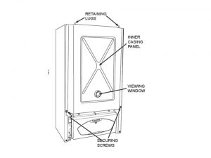
2. Remove the chamber cover by releasing all the screws (should be two) on each side. Those need to be lifted to release. Put those aside till the re-assmble part as shown on the picture below
3. Release the side panels by removing the screws on the upper and lower side
4. Remove the front panels by swinging them. While doing this lift the panels up
5. The comustion chamber should now be removed, It can be achived by unscrewing all four side screws
6. Put the front panel aside for the time of work performed. Re-assemble in reverse order
Domestic hot water sensor replacement
1. Isolate the appliance
2. Gain General Access -remove outer case front panel
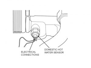
3. The domestic hot water sensor is located on the left side of the hydraulic block’s hot water side. Disconnect the leads from the sensor as shown on the picture below
4. Sensor should be removed by using 13 mm spanner
5. Put in the new sensor. Pay attention when fitting back the washer
6. All the leads to the replacement sensor should now be replaced
7. Re-assemble in reverse order
Central heating sensor replacement
1. Isolate the appliance
2. Gain General Access -remove outer case front panel
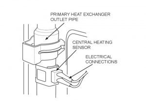
3. Locate the central heating sensor – it is on left side of the combustion chamber on the outlet of the primary heat exchanger as shown on the picture below
4. Unclip the sensor from the pipe
5. Disconnect the leads from the sensor
6. Fit replacement sensor
7. Fit the leads and replacement the sensor
8. Re-assemble in reverse order
Fan replacement
1. Isolate the appliance
2. Gain General Access -remove outer case front panel
3. Disconnect the electrical leads from the fan
4. To remove the fan, disconnect the 90º bend from the top of the boiler
5. Disconnect the electrical leads and air pressure switch connection tube from the fan. Release all screws connecting the fan into the fan-hood
6. Fit the new fan following reverse order logic. Re-connect sensing tube and all the electrical leads
7. Re-assemble in reverse order
Attention! Make sure that the earth lead is re-connected.
Air pressure switch replacement
1. Isolate the appliance
2. Gain General Access -remove outer case front panel
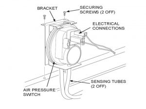
3. The air pressure switch is located on the top of the expansion vessel
4. Remove the sensing tube and electrical connections from the air pressure switch, noting which tube is connected to which port as shown on the picture below
5. Remove the air pressure switch by pulling forward off its bracket
6. Fit the replacement switch in reverse order of removal
7. Re-assemble in reverse order
Burner replacement
1. Isolate the appliance
2. Gain General Access -remove outer case front panel
3. Remove the burner assembly from the combustion chamber retaining all washers/gaskets for use on re-assembly
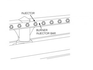
4. Remove the manifold as shown on the picture below. Fit the manifold with new burner injectors and tighten, ensuring that the injector size, marked on each injector is the same for the type of gas being used.
5. Replace the burner bar and re-fit the burner blades
6. Re-assemble the boiler in reverse order
7. If seals are damaged- replace as necessary
8. Verify boiler operation and gas soundness
Printed circuit board (PCB) replacement
1. Isolate the appliance and switch off the electricity
2. Gain General Access -remove outer case front panel
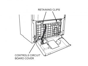
3. Remove the interface cover by lifting the two latches
4. Remove the electrical connections to the PCB by pulling carefully, noting the locations of all the terminals as shown on the picture below
5. Release the screws securing the PCB to the control panel and lift out the PCB
6. Fit the new PCB following reverse order logic. Make sure that all electrical connections are fit into the right home
7. Re-set if necessary the dip switches and the potentiometers to values of the old PCB
8. Re-assemble the boiler in reverse order
Pump replacement
1. Isolate the appliance
2. Gain General Access -remove outer case front panel
3. Remove the motor
4. Remove the secondary water-to-water heat exchanger
5. Remove the clop on the pump body and then release the pipe of the expansion vessel as shown on the picture below
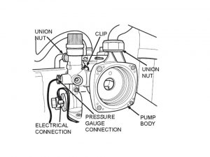
6. Release the connection of the pressure gauge
7. Disconnect the electrical leads of low pressure sensor
8. Release the outlet pupm fitting
9. All screws from the hydraulic block and pump located at the bottom of the boiler should be removed
10. Remove the pump assembly. Remove the pump body from the hydraulic assembly by releasing the clip
11. Fit the replacement body in reverse order ensuring that the pump washers are sound and fitted correctly and the polarity of the electrical connections are correct
12. Open the isolating valves on the low and return connections. Now re-pressurise, vent and re-fill the system as necessary. Make sure all joints are fitted
Water pressure sensor- low replacement
1. Isolate the appliance
2. Gain General Access -remove outer case front panel
3. The hydraulic circuit now needs to be drained
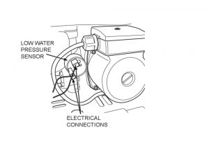
4. Remove the pressure sensor by turning it in an anticlockwise direction
5. Fit the replacement sensor in reverse order of removal ensuring all washers are fitted
6. Replace damaged washers as necessary
7. Open the isolating valves on the flow and return connections. Re-pressurise, vent and re-fill the system as necessary. Ensure all joints are sound.
8. Re-assemble the boiler in reverse order
Secondary Heat Exchanger replacement
1. Isolate the appliance
2. Gain General Access -remove outer case front panel
3. The hydraulic circuit now needs to be drained
4. Remove the two screws which connect the heat exchanger to hydraulic circuit
5. Remove the exchanger from the gap on the left hand side as shown the picture below
6. Fit the new heat exchanger checking that the plate numbers are the same. Re-assemble the boiler in reverse order. Make sure that all used washers are replaced if necessary
7. Open the isolating valves on the flow and return connections. Re-pressurise, vent and re-fill the system as necessary. Ensure all joints are sound.
Primary Heat Exchanger replacement
1. Isolate the appliance
2. Gain General Access -remove outer case front panel
3. The hydraulic circuit now needs to be drained
4. Remove the pipe clips on the pipes of heat exchanger
5. Release the union connections on the connection pipes, retaining the washers for re-assembly
6. The CH temperature sensor located on the return pipe should now be removed
7. The heat exchanger-three way connection valve pipes and the pump should now be removed
8. Remove the combustion chamber cover
9. Pull forward the heat exchanger and remove
10. Put in the new heat exchanger. Re-assemple in reverse order. Replace washers where needed
11. Open the isolating valves on flow and return connections, refill, vent and re-pressurise system ensuring the all joints are sound.
Gas valve replacement
1. Isolate the appliance
2. Gain General Access -remove outer case front panel
3. Ensure that gas supply to boiler is turned off
4. Disconnect the electrical connections to gas valve modulating coil
5. Release the connection from gas valve and manifold inlet, retaining the washers for use on reassembly as shown on the picture below
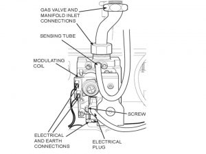
6. Release the main gas connection between the gas valve supply tube and gas inlet valve, retaining the washer for use on reassembly
7. Remove the gas valve’s two securing screws and washers from the underside of the boiler
8. Rotate the gas pipe and withdraw gas valve assembly
9. Refit in reverse order to removal, the polarity of the wires to the modulating coil is not important, replace any damaged washers as required
10. Check gas soundness and correct boiler operation